Sunrise alarm clock
A sunrise alarm clock with a little flair, to help me wake up on dark winter mornings. Easily assembled, to gift to friends in the same predicament.
Sunrise alarm clocks emit a gentle light, brightening gradually over a long period of time, emulating the sky’s slow transition from night to day. No more sudden (and rude) awakenings from a deep sleep.
My version would:
- double up as normal lighting for my desk area
- have some fun lighting modes and controllable brightness
- be controllable through my phone or laptop
- be printed on a PCB for easy assembly of a few units
- as a final bonus: the PCB would have an art silkscreen. Technology can be both bare bones and aesthetic.
Prototypes: breadboard to proto PCB
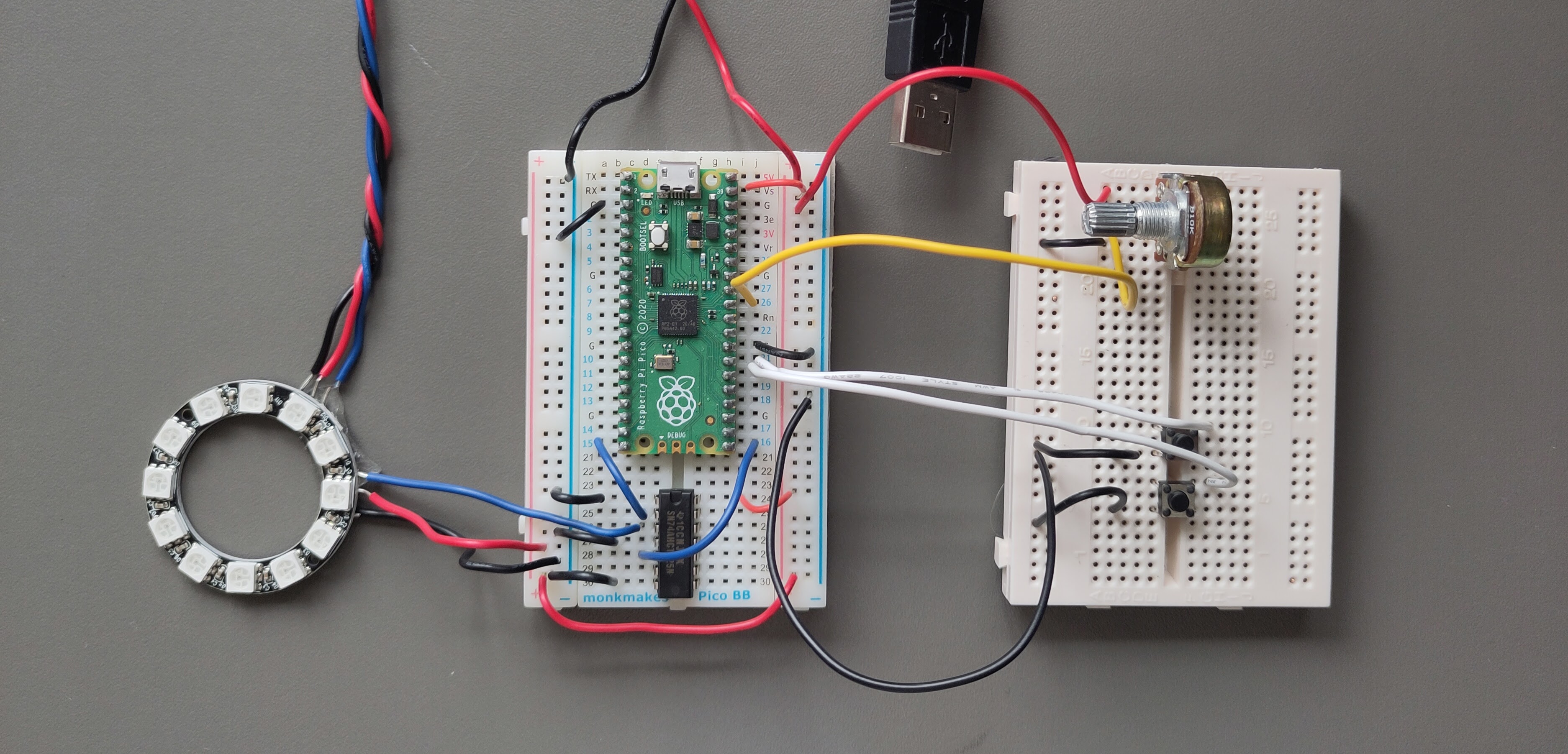
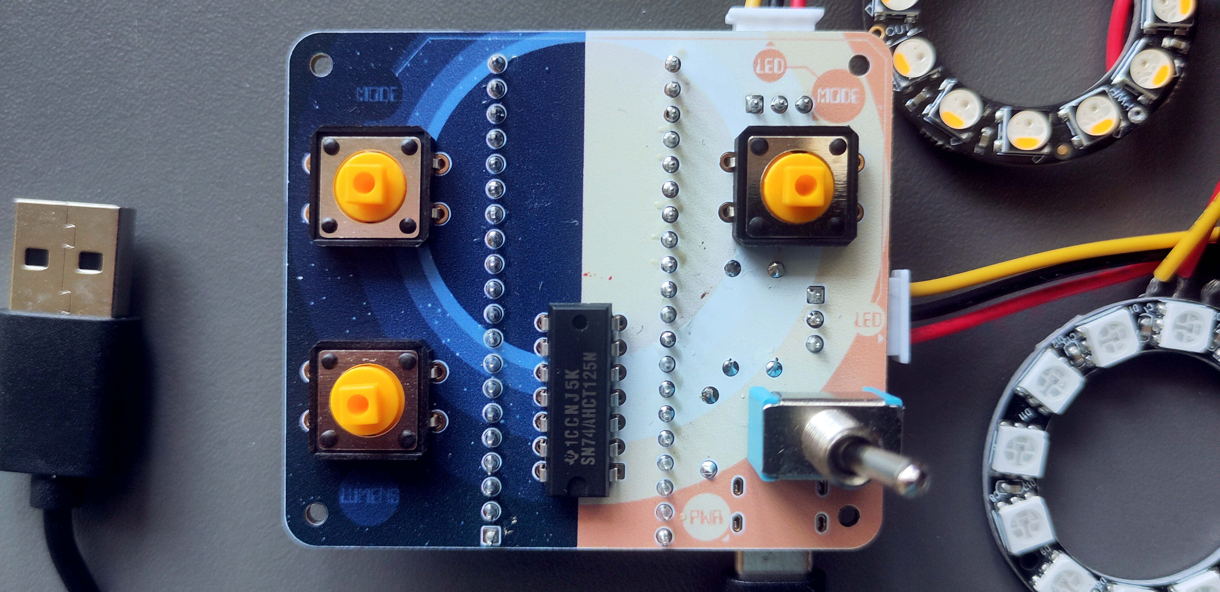
Breadboarding started with a spare Pi Pico, two NeoPixel LED rings, a logic level shifter (transforming data signals from the Pico’s 3.3V to the LEDs’ 5V). Buttons would control each LED’s ‘mode’ (Off / Steady white / Raindow dance), and a potentiometer would control all LED’s brightness.
Pico code was written in Micropython, and I played with a few dancing LED ideas to learn the ropes.
I envisaged that the potentiometer would work well as a brightness controller. However, the LEDs would flicker at a fairly high frequency, which was especially visible at low brightness. It worked better as a colour controller.
Plotting the potentiometer voltages, the signal was clearly noisy. I hoped that bolting everything down in the Proto PCB iteration might help with this - but it didn’t. Adding an RC filter likely would’ve helped.
Instead, I did away with the potentiometer and introduced a third push button. Holding it down would initially increase the brightness until I let go. The brightness would decrease on the next hold, and so on. This solved the flickering issues (caveat - after dealing with debouncing - more on that later).
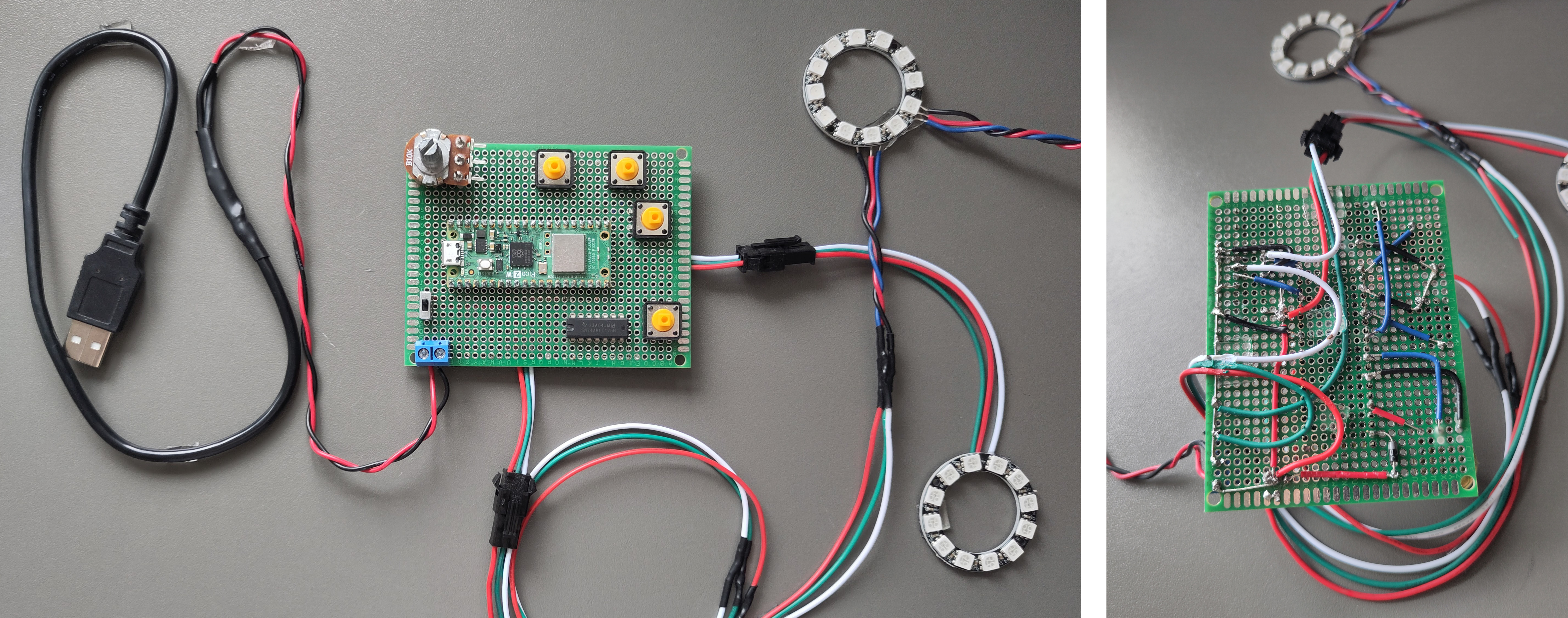
WiFi connectivity came at at this Proto PCB stage, with the Pico 2 W microcontroller. The Pico runs a HTTP server, serving a simple webpage. It allows control of the LEDs’ modes, brightnesses - and most importantly, the alarm time - from a web browser.
On setting the alarm time, the lights provide feedback both to say, “I got the message” and, “You’ve set the time to X!”. To communicate the latter, I made use of the fact there are 12 LEDs on the NeoPixel ring. The LEDs first light up to the alarm hour (if 3am -> light LEDs at the 12, 1, 2 and 3 o’clock positions), followed by the alarm minute (if 25 past -> light LEDs from 12, 1, through to 5 o’clock). This is shown in the video at the top of the page.
Final design: the PCB
At this stage, the last thing was to design and print the PCB version - a first for me.
I’d originally planned to do away with the Pi Pico dev board here. My intent was to almost copy-paste the various Pico components (i.e., the RP2350 microcontroller chip, memory, WiFi chip) from the dev board to my custom PCB - providing an opportunity to reverse engineer a production-quality PCB, design practice, and perhaps resulting in a more compact end product.
The main blocker to that plan was my lack of tools to solder the tiny surface-mount components on the dev board. So I’d have all the bits and pieces… but they’d have remained as a bag of bits! The Pico board therefore remains, and slots into the PCB.
Some component changes from the Proto PCB version included new LED connector types (which I could solder to the PCB), and a USB-C port for convenient power.
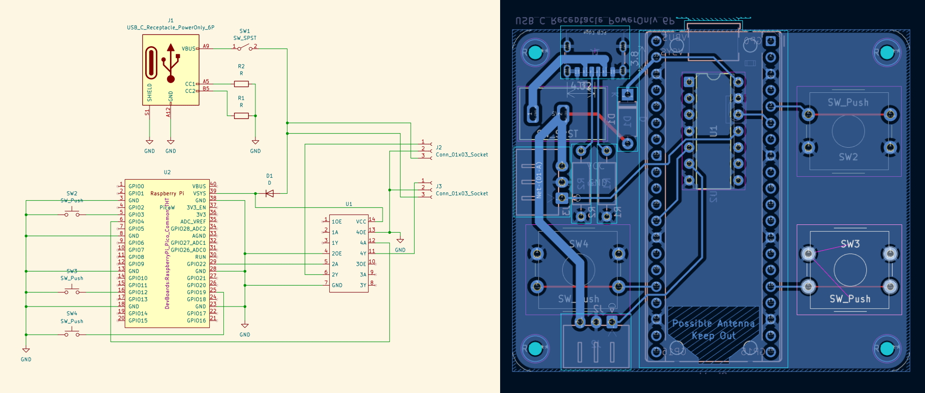
YouTube got me through the KiCAD and PCB design learning process. I found that if you’re clear enough with the schematic going into the process, learning to design PCBs is mostly a case of learning a new UI, and a few basics about PCB stackups (layers). Of course, this ended up being a fairly simple PCB, where I didn’t need to worry much about crosstalk (unwanted coupling between data traces) - but it was a good first project for that reason.
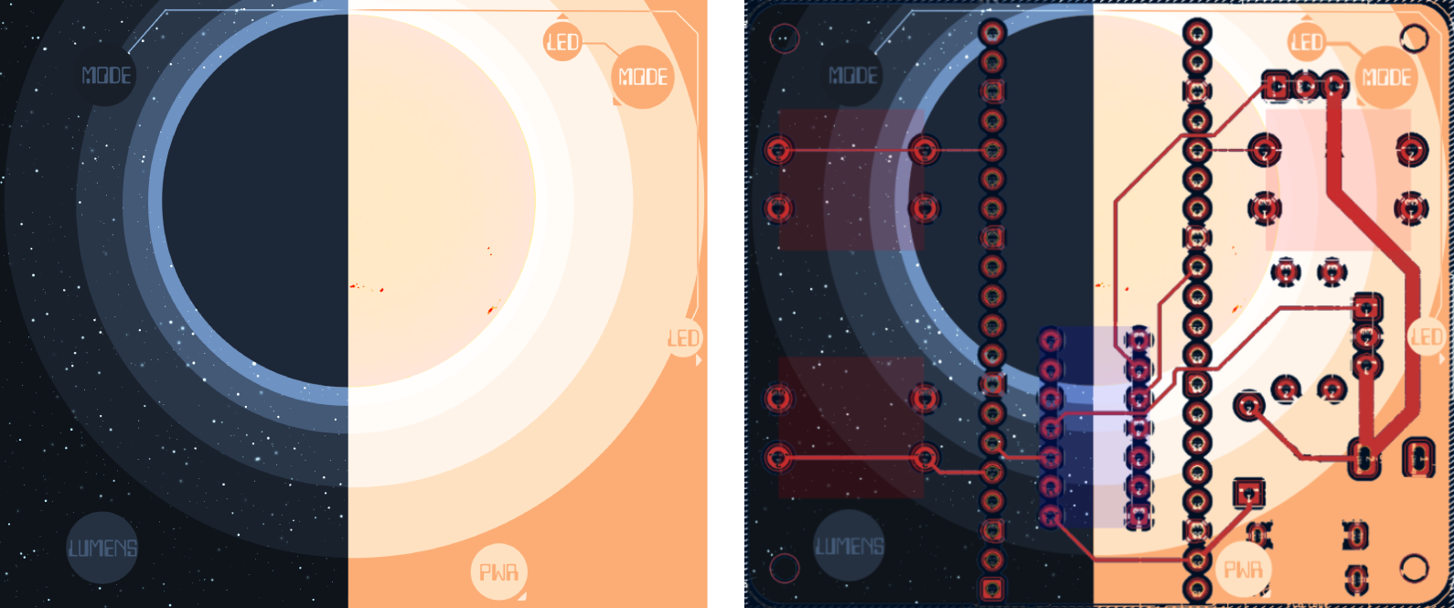
I added a multicolour silkscreen to my PCBs, designed in Photopea. The idea was to illustrate the sun, half shining and half-eclipsed. I was going for a bit of a sci-fi theme. Pairs of mode control buttons and LEDs are annotated. I’m happy with how the printed version turned out, though it lacked enough contrast to make the text pop and and the stars stand out.
Learnings & next iterations
MicroPython uasyncio
The microcontroller needs to handle multiple tasks simultaneously:
- Serving the webpage
- Listening for button presses & HTTP requests
- Changing the state of each LED independently (e.g. on / off / loop through the rainbow / countdown to the alarm time / gradually increase brightness)
Some of this could be split between the RP2350’s two cores, however smooth functioning wouldn’t be possible without an approach such as asynchronous programming - which is where uasyncio comes in (AKA asyncio in Python).
In my implementation, I only use one core (I found this alone able to run everything smoothly), with all the above tasks, and more sub-tasks, handled by different uasyncio coroutines.
For instance, while in the “rainbow” mode, the LED’s cycle through different colours. In each iteration, the code needs to advance the colours slightly, then sleep - otherwise it would all happen too fast to see. This sleep period is when other tasks can be carried out, such as responding to “events” from a button press or HTTP message, or even controlling the second LED string (this is technically called “yielding control” back to the event loop).
Uasyncio’s utility is evident with microcontrollers - I’ll certainly be using it in future projects.
Chips are better when they don’t all look the same
Two observations…
-
Chips can look identical, with near-identical names, and have exactly opposite functionality. Sounds great, right?
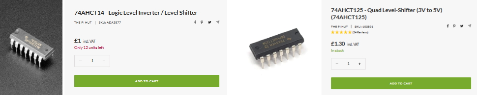
Shopping too hastily. I scratched my head till it hurt and pored over my PCB wiring a dozen times before realising why it didn’t work first time. I had ordered the 74AHCT14, not my intended 74AHCT125, for my logic leven shifters. Queue a massive d’oh moment.
The former is is a level shifter - lovely - and an inverter. Ah. It literally flips every 1 and 0.
I initially tried correcting by re-wiring (adding wires to account for the pinout differences), and updating the code to invert the inversion - requesting the opposite colour from the LEDs (like a double negative). This almost worked, but there’s no way to “invert” the data protocol cleanly with my code, as the data line isn’t just logical bits — it’s tightly timed 0 and 1 pulses. Inverting the signal messes with how the LEDs detect where messages start and finish. In the end I ordered the right component and assembled a fresh board.
-
Despite the low contrast I’m pleased with the addition of the art silkscreen. I like technology being visible, out on show, rather hidden behind a facade. It is a form of minimalism. Form and function combined. Plus, with the fun design, the PCB is uniquely mine rather than another generic PCB.
Power it properly
USB-C charging is smart. It can deliver a wide voltage and current range, with the amount negotiated between the device and the charger.
The correct way to negotiate the current supply is for the device (e.g. the Pico) to listen to what the supply can offer (e.g., “1.5A”), and limit it’s draw accordingly. This is safe - the device could then be plugged into any USB source. If the device doesn’t hear from the source (e.g. the source isn’t USB-C), it can limit itself to draw a safe amount (e.g 0.5A), and if it does, then it can limit itself to the supply’s maximum (e.g. 1.5A).
In a bit of haste, I decided to shortcut this formal negotiation by wiring 5.1K resistors to ground on the USB-C CC pins, and leaving it there. With this, 3A can be delivered from USB-C. However - it can also try drawing 3A, even if the supply can’t handle it. What happens next depends on how safe the charger is - hopefully, it has overcurrent protection and will limit the supply itself.
Relying on the safety net of the charger is obviosuly not ideal - my next iteration would fix this limitation.
Microcontroller choice
The Pico is a little overkill, with it’s 26 GPIO pins. An ESP32 C3 Super Mini would be smaller, cheaper, and I’m pretty sure do just as well. Not to mention, fewer headers to solder would be most welcome.
I would also like to try avoiding dev boards for final product, and rather integrating the microcontroller components directly onto my PCB. It wouldn’t necessarily make life easier or more convenient, or even save many pennies - but it would make the product more polished, and I’d learn more about PCB design and microcontrollers in the process.
Finishing touches
A few touches remain - lenses to diffuse the light, and improving on the current method of double sided tape for mounting the PCB to a wall or desk - which works well but feels very inelegant.